Application Requirements for Integrated Circuit Pins
I. Introduction
Integrated circuits (ICs) are the backbone of modern electronic devices, enabling complex functionalities in a compact form factor. These miniature electronic circuits consist of numerous components, including transistors, resistors, and capacitors, all integrated onto a single semiconductor substrate. One of the critical aspects of ICs is their pins, which serve as the interface between the IC and the external environment. The design and application requirements for these pins are paramount, as they directly influence the performance, reliability, and overall functionality of the integrated circuit. This blog post aims to explore the various application requirements for IC pins, providing insights into their types, electrical and mechanical characteristics, environmental considerations, design practices, and testing methodologies.
II. Understanding Integrated Circuit Pins
A. Types of IC Pins
IC pins can be categorized based on their functions:
1. **Power Pins**: These pins supply the necessary voltage and current to the IC, ensuring its operation.
2. **Ground Pins**: Ground pins provide a reference point for the circuit and complete the electrical circuit by connecting to the ground.
3. **Input Pins**: Input pins receive signals from external sources, allowing the IC to process information.
4. **Output Pins**: Output pins transmit processed signals to other components or systems.
5. **Bidirectional Pins**: These pins can function as either input or output, allowing for flexible communication between the IC and other devices.
B. Pin Configuration and Layout
The configuration and layout of IC pins are crucial for effective circuit design. Key considerations include:
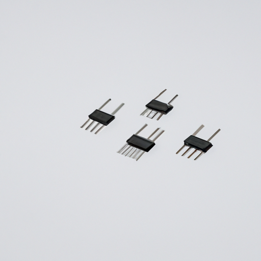
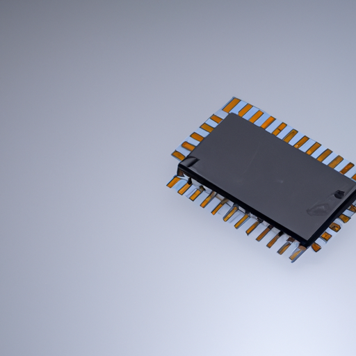
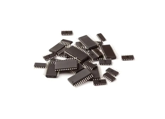
1. **Pin Count and Package Types**: The number of pins varies based on the IC's complexity and application. Common package types include Dual In-line Package (DIP), Surface Mount Device (SMD), and Ball Grid Array (BGA).
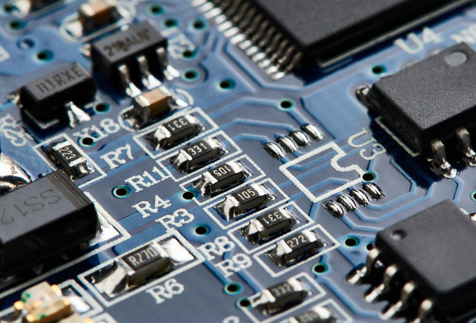
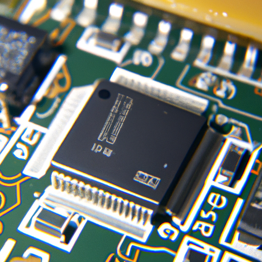
2. **Pin Arrangement and Orientation**: The arrangement of pins affects the ease of routing and soldering on printed circuit boards (PCBs). Proper orientation ensures that pins align correctly with corresponding pads on the PCB.
III. Electrical Characteristics of IC Pins
A. Voltage and Current Ratings
Understanding the electrical characteristics of IC pins is essential for ensuring reliable operation:
1. **Maximum Ratings**: Each pin has specified maximum voltage and current ratings that must not be exceeded to prevent damage.
2. **Operating Conditions**: The operating conditions, including voltage levels and current loads, should be within the specified limits to ensure optimal performance.
B. Impedance and Capacitance
The impedance and capacitance of IC pins play a significant role in signal integrity:
1. **Input Impedance**: High input impedance is desirable for input pins to minimize loading effects on the preceding circuit.
2. **Output Impedance**: Low output impedance is preferred for output pins to drive loads effectively.
C. Signal Integrity
Maintaining signal integrity is critical for the performance of ICs:
1. **Rise and Fall Times**: The speed at which signals transition from low to high (rise time) and high to low (fall time) affects the overall performance of the circuit.
2. **Signal Distortion and Noise**: Minimizing distortion and noise is essential for accurate signal transmission, which can be achieved through proper design and layout practices.
IV. Mechanical Requirements for IC Pins
A. Physical Dimensions
The physical dimensions of IC pins must be carefully considered:
1. **Pin Diameter and Length**: The diameter and length of pins affect their mechanical strength and solderability.
2. **Tolerance and Fit**: Tolerances must be maintained to ensure a proper fit with PCB pads, preventing issues such as misalignment or poor solder joints.
B. Material Considerations
The materials used for IC pins significantly impact their performance:
1. **Conductive Materials**: Pins are typically made from conductive materials such as copper or gold to ensure efficient signal transmission.
2. **Corrosion Resistance**: Materials must be resistant to corrosion to maintain long-term reliability, especially in harsh environments.
C. Thermal Management
Effective thermal management is crucial for IC pins:
1. **Heat Dissipation**: Pins must be designed to dissipate heat generated during operation to prevent overheating and potential failure.
2. **Thermal Expansion**: Consideration of thermal expansion is essential to avoid mechanical stress and ensure reliable connections.
V. Environmental Considerations
A. Operating Temperature Range
IC pins must be able to operate within specified temperature ranges to ensure reliability. Extreme temperatures can affect performance and lead to failure.
B. Humidity and Moisture Resistance
Resistance to humidity and moisture is vital for preventing corrosion and ensuring long-term reliability, especially in outdoor or high-humidity applications.
C. Chemical Resistance
IC pins should be resistant to various chemicals they may encounter in their operating environment, ensuring that they maintain functionality over time.
VI. Design Considerations for IC Pins
A. Layout and Routing
Proper layout and routing are essential for optimal performance:
1. **Trace Width and Length**: The width and length of traces connecting to IC pins affect resistance and inductance, impacting signal integrity.
2. **Grounding Techniques**: Effective grounding techniques help minimize noise and improve overall circuit performance.
B. Decoupling and Bypass Capacitors
Decoupling and bypass capacitors are critical for stabilizing voltage levels and filtering out noise, ensuring that IC pins receive clean power.
C. ESD Protection
Electrostatic discharge (ESD) can damage IC pins, so incorporating ESD protection measures is essential to safeguard against potential failures.
VII. Testing and Validation of IC Pins
A. Electrical Testing
Testing is crucial to ensure that IC pins meet specified requirements:
1. **Continuity Testing**: This test checks for proper connections between pins and their corresponding pads on the PCB.
2. **Functional Testing**: Functional testing verifies that the IC operates as intended under various conditions.
B. Mechanical Testing
Mechanical testing assesses the physical integrity of IC pins:
1. **Stress Testing**: This test evaluates the mechanical strength of pins under various loads.
2. **Thermal Cycling**: Thermal cycling tests the ability of pins to withstand temperature fluctuations without failure.
C. Reliability Testing
Reliability testing ensures that IC pins can perform over their expected lifespan:
1. **Life Cycle Testing**: This test simulates long-term use to identify potential failure modes.
2. **Failure Analysis**: Analyzing failures helps improve future designs and manufacturing processes.
VIII. Conclusion
In conclusion, the application requirements for integrated circuit pins are multifaceted and critical to the overall performance and reliability of ICs. From understanding the types and configurations of pins to considering their electrical and mechanical characteristics, environmental factors, and design practices, each aspect plays a vital role in successful circuit design. Adhering to these requirements not only enhances the functionality of integrated circuits but also ensures their longevity in various applications. As technology continues to evolve, future trends in IC pin design will likely focus on miniaturization, improved materials, and enhanced performance, paving the way for even more advanced electronic devices.
IX. References
1. Academic Journals
2. Industry Standards
3. Textbooks and Technical Manuals
This comprehensive exploration of the application requirements for integrated circuit pins provides a solid foundation for understanding their critical role in electronic design. By adhering to these guidelines, engineers and designers can ensure the successful integration of ICs into their projects, ultimately leading to more reliable and efficient electronic systems.

